MIL-PRF-2940D
controls of the storage oscilloscope, oscillographic recorder, or other data
acquisition system should be set that recorded signals are at least 50 percent
of full scale. Except for the dampening tests which require a specific fill
fluid, the others may employ fresh water as the fill fluid. If fresh water is
used as the fill fluid for the temperature test, provision should be made to
employ a suitable additive to prevent freezing. As applicable, the snubber
should be thoroughly cleaned prior to conducting the dampening test. The fill
fluids for the dampening test shall be as follows:
(a)
Type 1: 2190-TEP oil in accordance with MIL-PRF-17331
an equivalent oil may be substituted).
(b)
Types 2 and 4: Fresh water.
(c)
Type 3: Air or nitrogen.
Unless otherwise indicated, the pressure transducer or pressure gauge shall be
connected to the output side of the snubber with only an adapter fitting
between them. Except where temperature is a variable, the tests in this
specification shall be conducted at an ambient temperature of 75 + 10°F.
4.6.1 Steady state transmission. A reference measurement shall be made
employing either a pressure transducer or pressure gauge, both with and
without a snubber. The reference measurement shall be made both upscale and
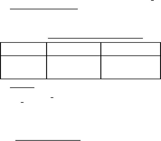
down scale at the test pressures for the applicable class (see 1.2) as shown
in table III. The snubber shall meet the requirements of 3.4.1.
TABLE III.
Steady state transmission pressures.
Snubber class
Operating range
Test pressures
(see 1.2.2)
(psi)
(psi)
L
10/1000
10, 250, 500, 750,
1000
H
1001/6000
1200, 2400, 3600,
4800, 6000
4.6.2 Dampening. The dampening test shall be conducted utilizing an
apparatus similar to that shown on figure 1. A step change shall be made from
atmospheric pressure to 200 + 10 psi for class L snubbers and from atmospheric
pressure to 1500 + 100 psi for class H snubbers. The pressure step change
shall be accomplished in 100 milliseconds or less as measured with the
monitoring pressure transducer. Both the test and monitoring pressure
transducers shall have frequency response characteristics sufficient to
respond to and produce an electrical signal output in response to a full scale
pressure change occurring in 10 milliseconds or less. The snubber shall meet
the requirements of 3.4.2.
4.6.2.1 Dampening test procedure. The following procedure, applicable
to figure 1, may be used to perform the dampening test:
(a)
Ensure that V2 and V4 are closed and that V3 is open.
(b)
Utilizing V3, introduce the fill fluid, as applicable into
the monitoring and test transducer legs. Loosen the
fittings at T1 and T2 to ensure a complete fill. Tighten
all transducer fittings and close V3 after the fill
procedure is complete.
(c)
Utilizing V1, pressurize the high pressure reservoir with
nitrogen to a value sufficient to ensure that the pressure
step change in the transducer legs will satisfy the criteria
of 4.6.2. Close V1.
(d)
Energize the transducers and applicable monitoring equipment,
8
For Parts Inquires call Parts Hangar, Inc (727) 493-0744
© Copyright 2015 Integrated Publishing, Inc.
A Service Disabled Veteran Owned Small Business